I’ve been fighting with this issue on and off for months. I’ve spent the past 3 days doing almost nothing except trying to figure this out.
Months ago I was trying to use a program called stm32flash to flash firmware onto an STM32 chip from a Raspberry Pi. It usually worked the first time I used it. It consistently failed the second time. I had to reboot before it would work again.
Because decyphering other peoples’ code is sometimes challenging, I decided I should just write my own program in Python, because the rest of the test suite was already written in python. Then I found stm32loader. This is a python based stm32 flasher. I was able to load it as a module into my test suite and use it to flash the STM32. This was great. It worked, and I spent several days writing the rest of the test code.
When I finally was finished and ready to start testing boards, the stm32loader bit stopped working. I did some debugging and discovered it was getting a NACK from the STM32 when it should have been getting an ACK. Obviously there was some communication issue.
I spent a day working at it from the software side, with no progress. The sad thing is, it would sometimes work. It would sometimes work many times in a row. But, then it would sometimes not work. When it didn’t work, it usually didn’t work for many times in a row. But, it was completely inconsistent. I couldn’t find any pattern.
Finally, I hooked an oscilloscope up to the uart traces on the board under test and tried to watch the failed communications. I was able to see a few bytes of communications, but while the scope was hooked up, the code never failed.
So, I figured I should just start testing boards. Of course, the first board I wanted to test failed. It was time to bring out the big guns.
I dug out my ADM2 and made up some test clips to monitor both RX and TX on the device under test. It didn’t fail for a dozen or so attempts.
Then, it failed! And I captured the entire communications! And I found the issue!
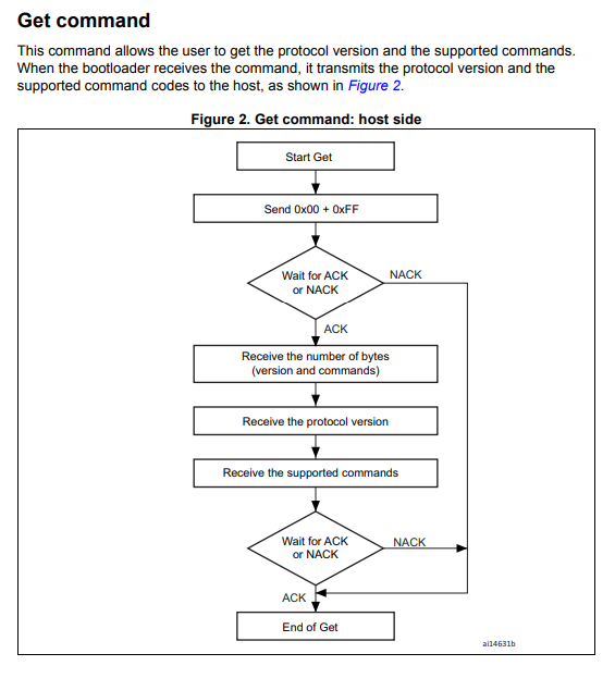
To put the STM32 into bootloader mode, you hold the BOOT0 pin high then reset or power up the STM32. To access the bootloader over the UART, you then send the byte 0x7F. The STM32 detects this, uses it to set the baud rate, and responds with an ACK. (0x79).
Once it is in UART bootloader mode, you can begin to send commands. Each command is sent as two bytes. The command byte and a checksum, which is that byte XOR 0xff. (in other words, invert all the bits) For example, you can send 0x00 0xff (GET) to request some basic info from the STM32. It is supposed to respond with an ACK then some data.
Here is what I captured with the ADM2. You can see the request to go into UART bootloader mode, and the STM32 responds with ACK. So far so good.
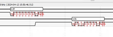
However, for some unknown reason, stm32loader then sends another 0x7F a bit later.
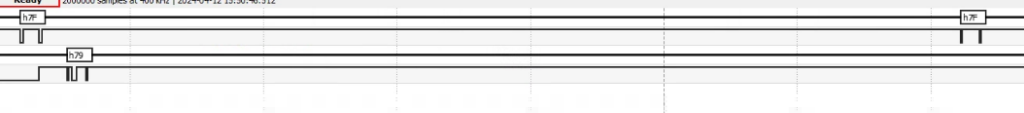
Since the STM32 is now in “command mode” it is waiting for TWO bytes. It doesn’t respond to the 0x7f at all.
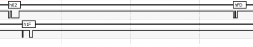
Then, I request GET_ID by sending 0x02 0xfd. You can see the STM32 immediately responds 0x1F to the first byte of the command. It still had the 0x7f in the buffer and now got the second byte 0x02 which is NOT a valid checksum, so it responded with NACK. stm32loader isn’t listening, yet, though, because it is still sending the “command”… it sends 0xfd. THEN, it finally reads the incoming buffer and finds a NACK. So, it sends 0x02 0xfd again. And, again, because there’s already 0xfd in the buffer, when it gets 0x02 (which actually IS a valid checksum, this time… but 0xfd is not a valid command) it immediately sends 0x1f again, and the cycle continues.
By this time, I could have written my own code to program the STM32. It’s what I should have done, but I got lazy and that bit me.
Leave a Reply
You must be logged in to post a comment.